OLE Nepal’s team of network engineers have been putting a lot of effort into connecting all 26 program schools in six districts to a school intranet. Amongst many advantages of such a network are the facility to monitor and update school servers remotely from OLE Nepal office and the ability to establish free and direct communication link between the schools and OLE Nepal.
Since most part of the country does not have any communication link to the outside world, we have had to design and install network connections from scratch. In most of the hilly regions, wireless technology is the preferred medium due to its low initial cost of installation and ease of maintenance. Furthermore, using hilltops we can eliminate the need for building tall towers to get a clear line of sight between two network nodes. We have used mostly Mikrotik devices for long range wireless connections, and we had been quite satisfied by its performance. However, recently we were a bit concerned when few devices suddenly started malfunctioning in Makwanpur, Dadeldhura, and Kapilvastu districts. Our investigation revealed that the devices were damaged by lightning strikes.
We then set out to protect the devices against lightning strikes. First, we placed spike suppressors at all the schools and relay points. A spike suppressor is typically used in between the main power supply and the UPS System. When there is a voltage spike, the circuit automatically breaks and saves the electronic equipment from being damaged. We also implemented a multi-level earthing system at the relay points so that the exposed conductive surfaces are at the same electrical potential as the surface of the earth.
Why Earthing?
One of the major tasks of earthing is to ensure the safety of persons during fault conditions. Earthing creates the path of least impedance from system components to the earth so that any surge that occurs is dissipated quickly. It allows the lightning strike energy to be safely dissipated, thereby minimizing the danger caused by the lightning. Earthing is key to safety—protection of personnel, equipment, and facilities. Another advantage of earthing in communication towers is to reduce electromagnetic interference.
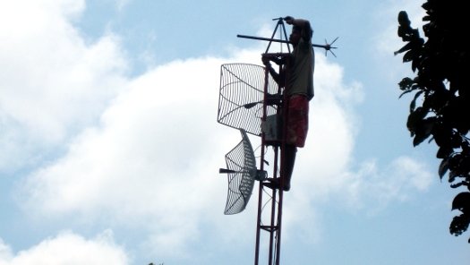
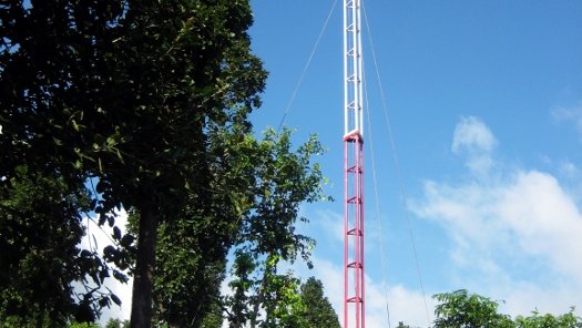
Weather experts report that lightning strikes the earth 100 times each second around the world. The regions most prone to lightning are those where moist and unstable air masses move. Since communication antenna/towers are placed at the top of the hills or at the highest points, they are more susceptible to lightning strikes.
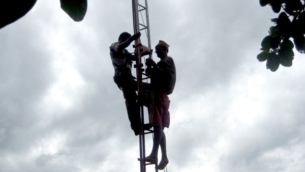
In the past, we were having problems with many antennas, especially in remote hilly regions, with motherboards getting burned out. The reason behind this was insufficient protection circuitry. In order to avoid this problem repeating itself and to protect expensive antennas from lightning, we decided to provide earthing, and we started it from Manakamana Danda [hill] in Makwanpur.
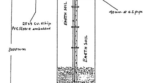
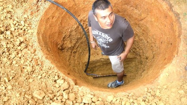
PROCEDURE FOLLOWED WHILE INSTALLING COPPER PLATE EARTHING AT MANAKAMANA DANDA